Learning Based Toolpath Planner on Diverse Graphs for 3D Printing

SIGGRAPH Asia 2024 (ACM Transactions on Graphics)

Yuming Huang1, *, Yuhu Guo1, *, Renbo Su1, Xingjian Han2, Junhao Ding3, Tianyu Zhang1, Tao Liu1,
Weiming Wang1, Guoxin Fang3, Xu Song3, Emily Whiting2, Charlie C. L. Wang1, †

1. The University of Manchester, United Kingdom
2. Boston University, United States
3. The Chinese University of Hong Kong, Hong Kong SAR., China
* Equal contribution of the first two authors
† Corresponding author (Email: changling.wang@manchester.ac.uk)


This paper introduces a reinforcement learning-based planner that optimizes 3D printing toolpaths for large-scale applications, demonstrating generality and efficiency across different printing processes with significant improvements in printing quality and deformation.

Abstract

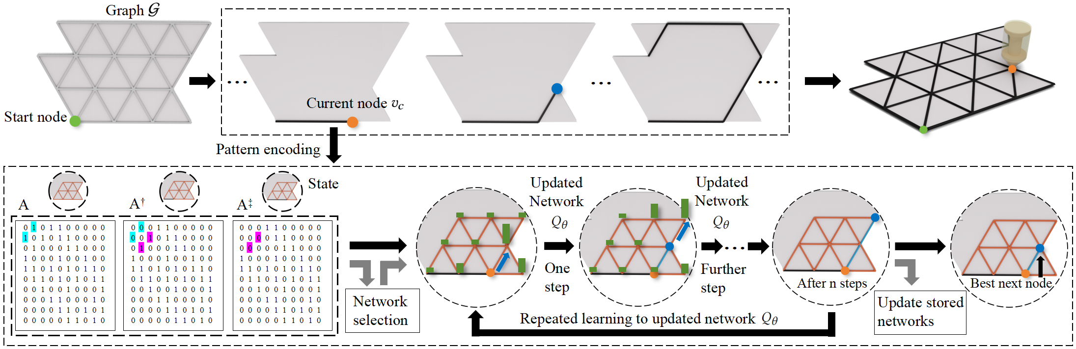
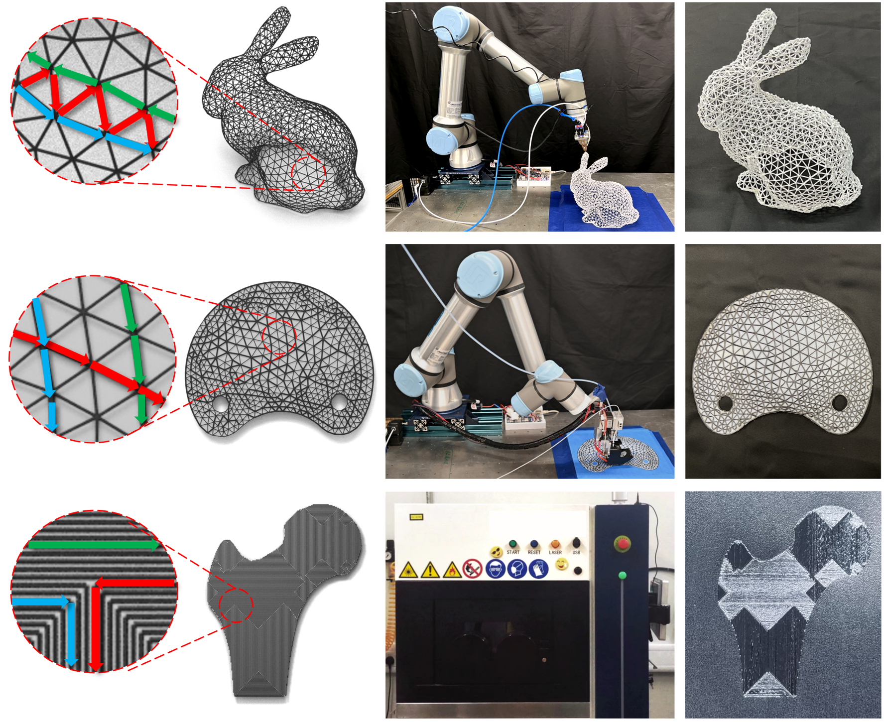
We presents an efficient reinforcement learning (RL) based planner for computing optimized 3D printing toolpaths, which can work on graphs on large scales by constructing the state space on-the-fly. The planner can cover different 3D printing applications by defining their corresponding reward functions and state spaces. Toolpath generation problems in wire-frame printing, continuous fiber printing, and metallic printing are selected 
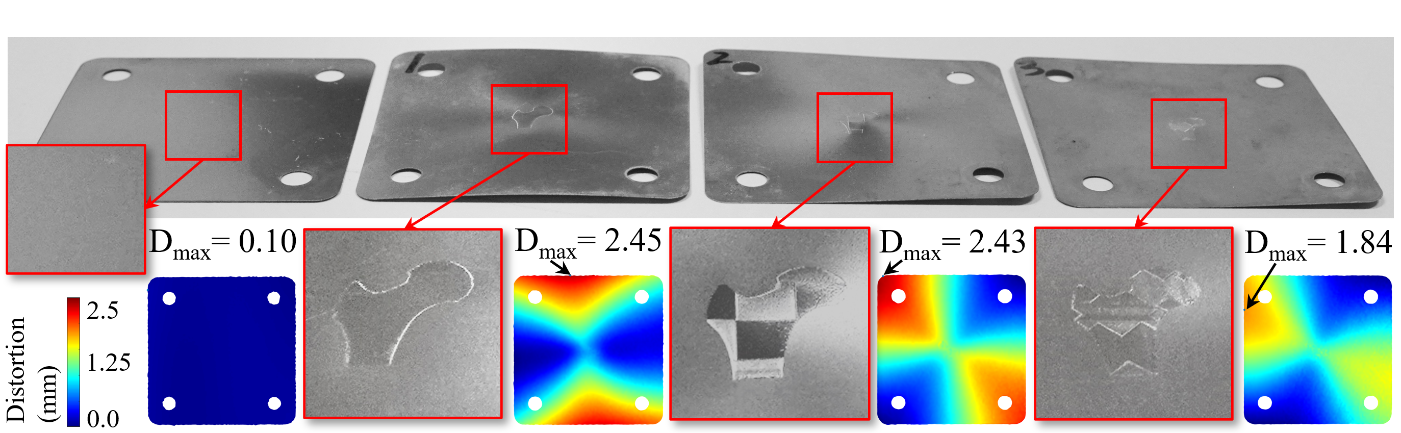
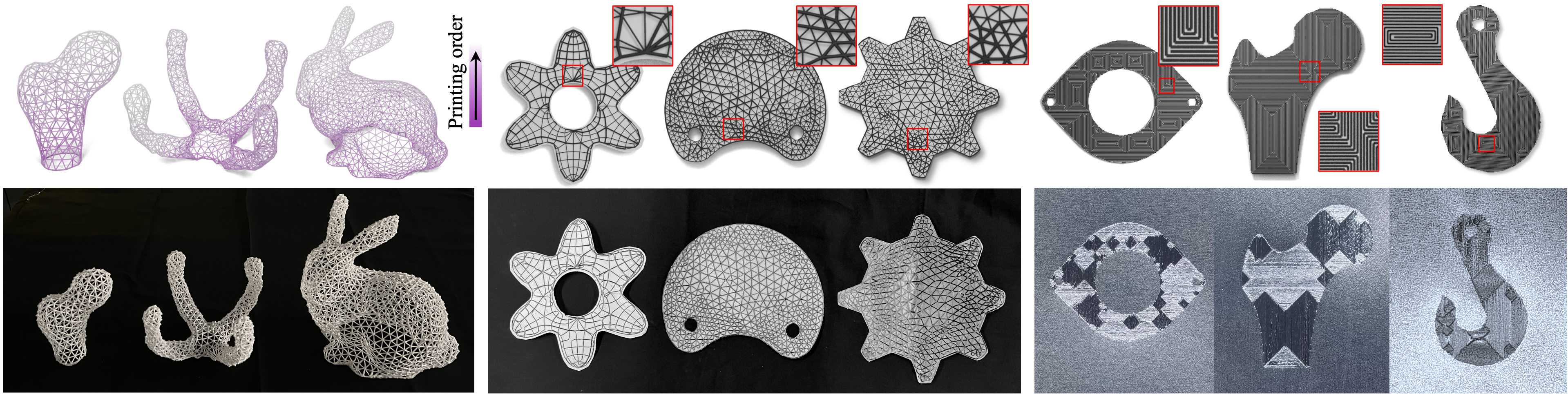
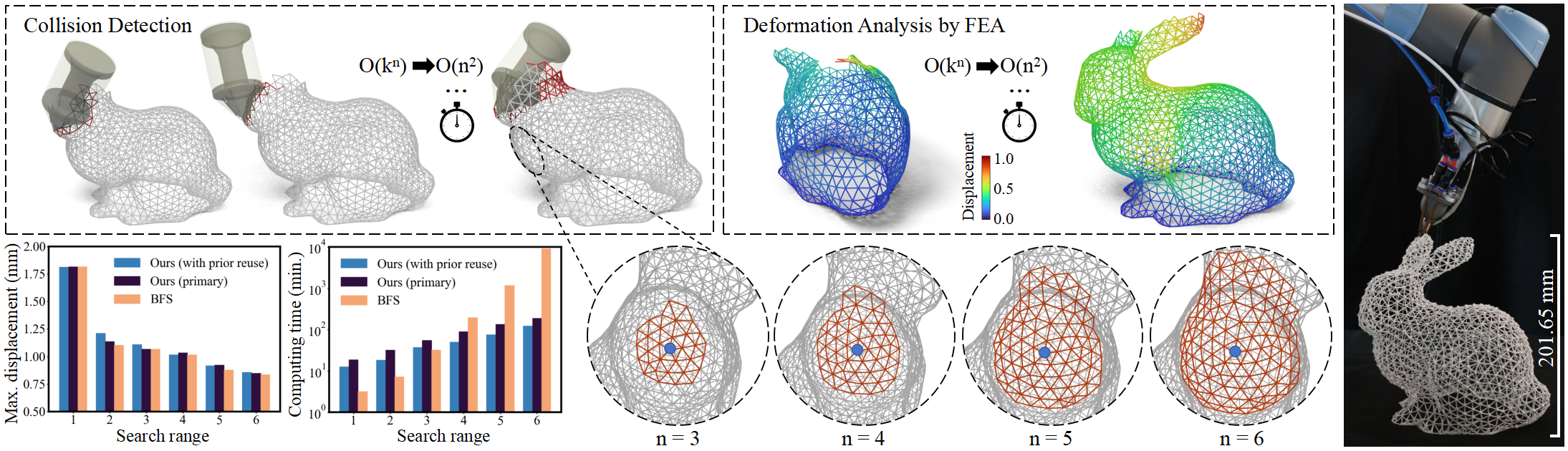
here to demonstrate generality. The resultant toolpaths have been applied in physical experiments to verify the performance of the planner. By this planner, wire-frame models with up to 3.3k struts can be successfully printed, up to 93.3% of sharp turns on continuous fiber toolpaths can be avoided, and the thermal distortion in metallic printing can be reduced by 24.9%.

How our system works


This illustration shows how our Q-learning based planner computes the toolpath on a graph \(\mathcal{G}\). The planner explores \(\mathcal{G}\) on a Local Search Graph (LSG) with n-rings of neighbors (n=2 in this example), starting from a given current node vc (highlighted in orange). The moving state S of vc is a 3D matrix determined by the current LSG and two previous steps in the partially planned toolpath (shown in black). This state is formed by three adjacency matrices A, A, and A. The next best node for vc is determined by an updated deep Q-network, which computes the Q-values (indicated by green bars) for every node in the LSG based on the state S*. Color blocks highlight the differences between A and A (pink) and between A and A (blue). The best next node becomes the new current node, and by repeatedly applying this Q-learning based planner, the resultant toolpath is determined.


Overview


Applications in computing optimized toolpaths for 3D printing problems of wire-frame models, the continuous fiber reinforced layer for Carbon Fiber Reinforced Thermoplastics (CFRTP), and Laser Powder Bed Fusion (LPBF) based metal printing. Given input graphs, our planner can generate toolpaths optimized according to manufacturing objectives. The toolpaths have been tested in physical experiments to produce the results. Three different parts of the toolpath are visualized as red, green, and blue arrows.


Experimental results


Comparisons of CCF printing for tensile test

Comparisons of CCF printing for the Shell model: (top) the toolpath generated by the dual-graph based DFS method and (bottom) our toolpath. As the number of sharp turns have been significantly reduced on our toolpath, stronger mechanical strength is observed in the tensile test. Specifically, specimen fabricated by our toolpath shows 29% increased breaking force while using 28% less CCF.


Comparisons of wireframe printing

Comparison of the printing results of two models by using the toolpath generated by peeling heuristic vs. the toolpath generated by our RL-based planner. When using the peeling-like toolpath, we can observe the failure cases of large bending deformation on struts, i.e., with large displacements caused by gravity. Also, stringing phenomenon occurs due to frequent lifting of the tool.


Comparisons of metallic printing for thermal warpage study

Thermal warpage study using different toolpaths to print the Femur model on the initial plate, including the zigzag toolpath, the chessboard toolpath and our toolpath. Distortions are measured by 3D scanner and displayed as colormaps. Distortion on the initial plate is 0.10mm. Maximum distortion on the specimen printed by our toolpath is 1.84mm, which is reduced by 24.90% and 24.28% compared to the zigzag toolpath (2.45mm) and the chessboard toolpath (2.43mm).


All fabrication results

Our method has been tested on a variety of models by incorporating the manufacturing objectives in different applications: wire-frame printing, CCF printing for CFRTPs, and LPBF-based metallic printing. (Top Row) Computational results for toolpath planning. (Bottom Row) Fabrication results for the corresponding models.